
STL vs STEP: 3D Files for Game Pieces
 By Hersh Glueck
STL vs STEP is the first question for any plastic game piece, and the short answer is this. A STEP file (also written STP) is an exact CAD model made of mathematical curves and surfaces, and the factory can edit it. An STL file is a mesh of small flat triangles, like a video game model, and it cannot really be edited. Send STEP for simple and functional pieces; STL is fine for detailed sculpted miniatures. This guide explains both files and then the design rules that decide whether a mould can make your piece at all.
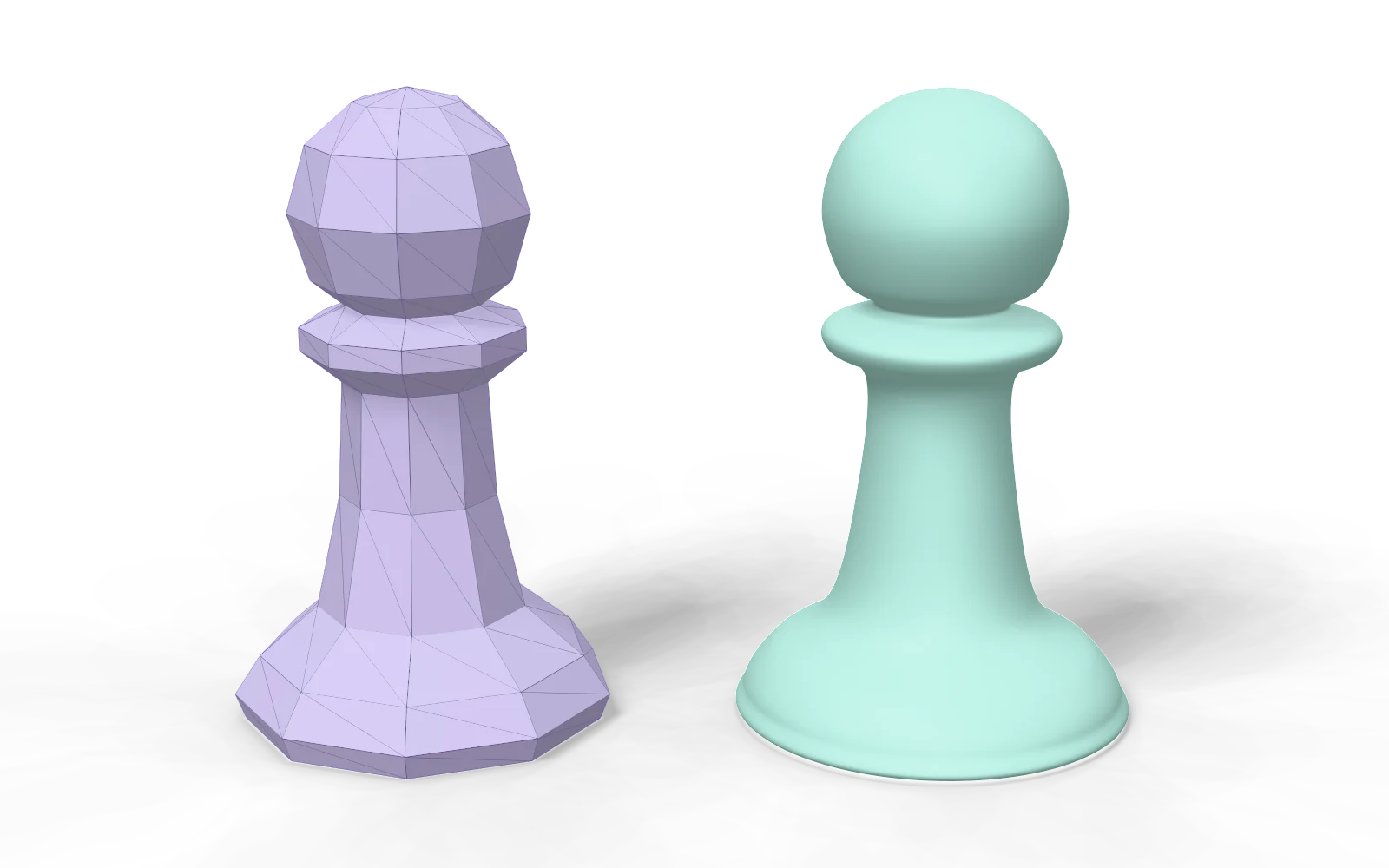
What Is an STL File?
An STL file describes a 3D shape as a mesh of flat triangles. STL stands for stereolithography, an early 3D printing method, and it is still the standard file for 3D printing. It works like a flattened image: you can view it and print it, but it does not keep the lines and structure of the design, so it cannot be edited properly. A curve in an STL is really many small flat faces, so a low-quality STL shows facets on the finished piece. If you send an STL, make it high resolution. You can open an STL on most computers without special software.
What Is a STEP File?
A STEP file describes a 3D shape with exact curves, surfaces and dimensions. STEP stands for Standard for the Exchange of Product Data, and the files end in .step or .stp, so STL vs STP is the same question. CAD and CAM programs (computer-aided design and manufacturing) read it, and it keeps the editable raw data: the lines, the structure and the specifications. To view one without CAD software, use a free viewer such as ABViewer or eDrawings.
Which File the Factory Needs
Factories prefer STEP, because their mould designers work in CAD. With a STEP file they can make small fixes and design the mould parts directly. That lowers adjustment fees, lowers the risk of the file being rejected, and avoids remaking the model, which costs money and can lose quality. A simple mould is carved by a CNC machine straight from the STEP and CAD files.
STL still has its place. Most character artists sculpt in programs that make meshes, not CAD models, and a detailed miniature is easier to sculpt that way. Its mould is then usually cast from a sculpt rather than carved, sometimes by a factory with special equipment, which can cost a little more. That extra cost is worth it for premium pieces such as hero miniatures and display figures. For everything simpler, such as functional parts, containers and minimal figures, a STEP file is strongly recommended. Either way, send at least an STL with your quote request, because a 3D file is needed for an accurate price.
| STL | STEP (STP) | |
|---|---|---|
| Made of | Flat triangles (a mesh) | Exact curves and surfaces |
| Like in 2D | JPEG, PNG (raster) | SVG, AI (vector) |
| Factory can edit it | Hardly | Yes |
| Made in | Sculpting programs | CAD programs |
| Best for | Detailed miniatures | Simple parts, CNC moulds |
Converting Between STL and STEP
Converting STEP to STL is easy; STL to STEP is hard and best avoided. Think of 2D files: a vector image turns into pixels with one click, but turning pixels back into clean vectors loses detail. 3D is the same. Almost any 3D format (OBJ, FBX, STEP) converts to STL. Converting an STL to STEP usually wraps the triangles in surfaces without making a real CAD model, so it does not help the factory much. If you can, design in the format the factory needs from the start.
How an Injection Mould Opens
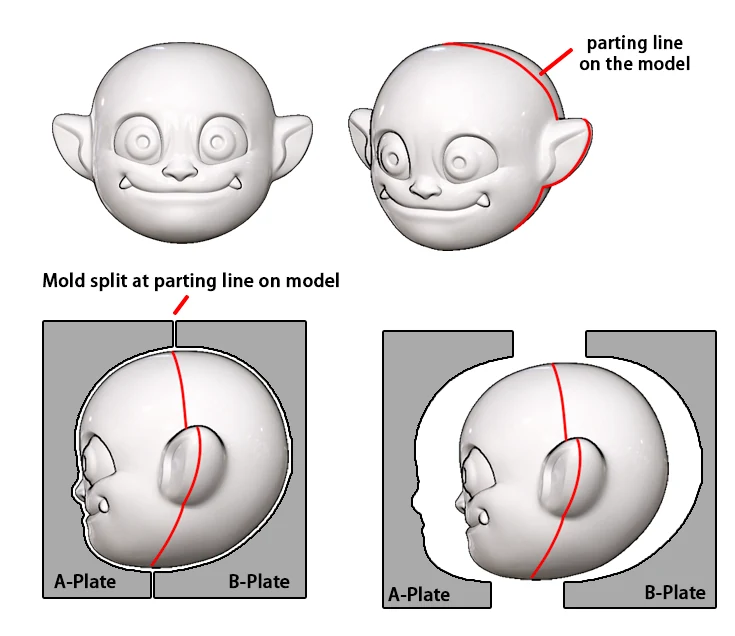
Every design rule below comes from one fact: the mould must open and let the piece out. A simple injection mould has two halves, the A-plate and the B-plate. They clamp together, plastic is injected into the hollow between them, and where they meet they leave one line all around the piece: the parting line. Then the plates pull apart and the piece is pushed out. Design for injection molding means designing so that this can happen.
Undercuts
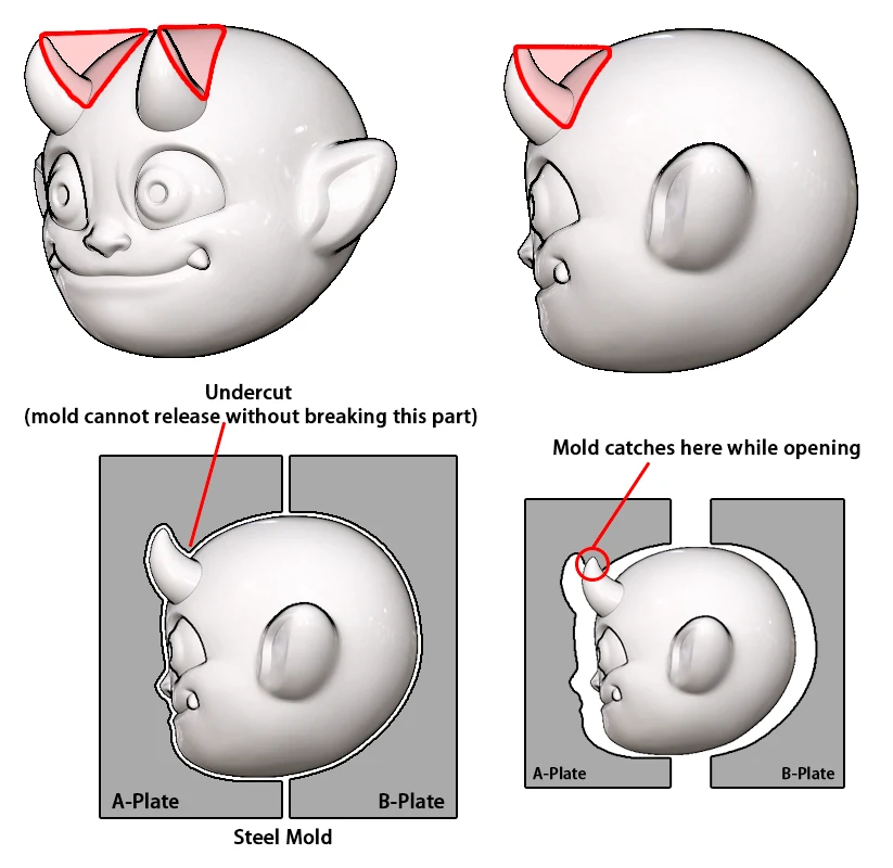
An undercut is any part of a piece that hooks into the side of the mould, so the mould cannot open without breaking it. Here is a useful trick: imagine every empty space around your piece as solid steel. A horn curving out of a demon's head has air under it on screen, but in the mould that air is steel. When the mould opens, the horn catches on the steel and breaks, or the piece sticks in the mould.
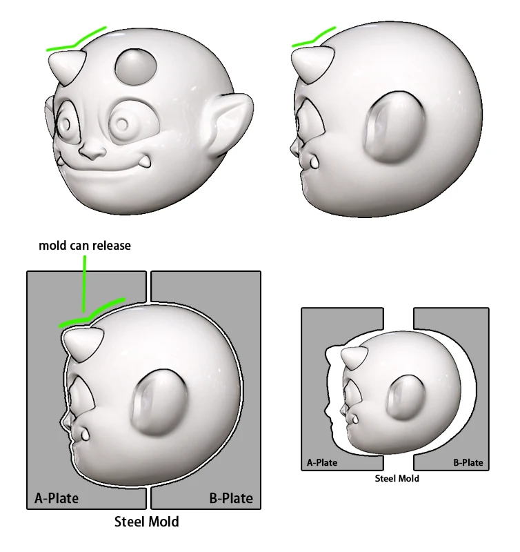
The fix is a redesign that keeps the character: here the horns are turned so they point away from the mould's opening direction. Every piece is different, so the fix depends on the part and on the 3D designer. When an undercut is truly needed, sliders (also called slides or lifters) can be added to the mould to release it, but they add tooling cost, so avoid them unless the piece cannot work without one. Undercut injection molding with sliders is a last resort, not a design habit.
Soft PVC is often used for character miniatures because it flexes as it leaves the mould. That allows small undercuts: under 0.5 mm for automatic release. Larger undercuts need the piece to be pulled out by hand, which raises the cost per piece. The deeper the undercut, the softer the PVC must be.
Overlapping Parts
Overlapping parts are undercuts that are easy to miss. Imagine a wizard holding a staff. If the staff is held at his side, the two plates can release it. If he holds it out in front of his body, there is a gap of air between the staff and the robe, and in the mould that gap is steel. The staff locks the piece into the mould.
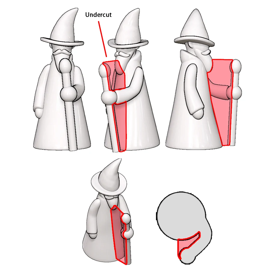
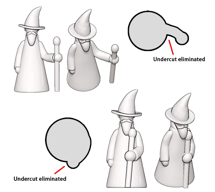
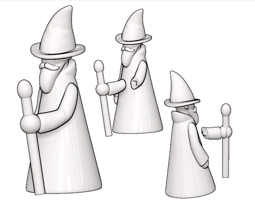
There are three fixes. Move the staff to the side of the body; move it close against the body, so there is no gap; or, if the pose matters, cut the piece into parts that are moulded separately and glued together in production. Assembly leaves a seam, which a good artist can often hide in the design, and it adds hand work to every piece.
Draft: Angled Sides
Faces that slide against the steel as the mould opens should be slightly angled, not perfectly straight. This angle is called the draft angle, and it lets the piece release without scraping. A draft of 1 to 2 degrees is usual for smooth faces; textured faces need more. Pieces that should drop out automatically need enough draft, no undercuts, and enough strength to be pushed out without damage.
Wall Thickness
Wall thickness is the distance between one surface of a piece and the other, and its thinnest point is where it breaks. A minimum of about 2 to 3 mm is a reasonable rule; it varies by material. A short tapered stub can safely narrow to 1 mm or less, but a long thin rod snaps if it gets too thin. Avoid a thick section that narrows into a thin neck and then thickens again: a 5 mm rod that narrows to 2 to 3 mm in the middle is a weak point that breaks.
Keep walls as even as you can. Thick solid parts cool slowly in the middle, and as plastic cools it shrinks. Uneven cooling causes warping, sink marks and hollow voids, and makes each moulding cycle longer, which raises the unit cost. Hollow out large solid parts and keep them strong with ribs or a lattice inside. On a miniature, the underside or base is the best place to hollow. For very large, thick pieces, the model can be split in half, hollowed to an even 2 to 3 mm wall, and the halves welded together by ultrasonic welding: less plastic, less weight, no warping.
Centre of Gravity
A standing figure must keep its centre of gravity over its feet, or it falls over. Larger feet make a figure more stable. In an extreme pose, add another contact point with the ground, such as a tail or a weapon resting on the floor: three contact points that surround the centre of gravity make a stable stand. The surest fix is a base, as long as the centre of gravity sits over it. A top-heavy figure, like a lollipop on its stick, can still tip over in play, so keep the weight low. Test the balance with a cheap 3D print before you make the mould.
Scale: Choose It Early
Decide the final size of a piece before you design it, because changing scale later changes more than the size. Volume grows with the cube of the scale: double the height of a piece and it uses about eight times the plastic. Scaling down also thins the walls in proportion: a 10 mm piece with 2 mm walls, shrunk to 5 mm, has 1 mm walls, which is often too thin to mould. Fixing that afterwards means remodelling the piece.
A Watertight (Manifold) Mesh
A mould can only be made from a model that could exist as a real, solid object. In 3D software it is easy to make surfaces that cannot exist: faces with no thickness, holes in the mesh, or surfaces that cut through each other. The model must be a manifold mesh, often called a watertight mesh: one closed, continuous volume with no holes, self-intersections or zero-thickness faces. Most 3D programs can check this for you, so run the check before you send the file.
Checklist Before You Send a 3D File
- STEP for simple and functional pieces; a high-resolution STL for sculpted miniatures.
- Final scale decided and the model built at that size.
- No undercuts across the parting line, or only small ones on soft PVC.
- No gaps between limbs, weapons and bodies, or the piece split into parts.
- Draft on faces that slide against the mould.
- Walls about 2 to 3 mm and as even as possible; thick parts hollowed.
- Centre of gravity over the feet or a base.
- A watertight, manifold mesh.
- A 3D print to test the fit and the balance.
A 3D designer who understands injection moulding and talks directly with the factory saves the most money, because the piece is right from the start. We work with Jordan O'Neill, a 3D designer in the UK who prepares files for production. Materials, mould costs and prototypes are in our guide to board game miniatures, and flat cut pieces in what is a CAD file. To have your files checked, contact us.
Frequently Asked Questions
What is the difference between STL and STEP?
Which file should I send for injection moulding?
Can I convert STL to STEP?
What is an undercut in injection moulding?
How thick should the walls of a plastic game piece be?
Talk to Our Team About Creating Your Board Game
From design to manufacturing, we can help you with every aspect of turning your game concept into reality.